How to use the fiber optic attenuator?
 A fiber optic attenuator is a passive device used to reduce the power level of an optical signal in a fiber optic network. It ensures that the signal strength is within the optimal range for the receiving equipment, preventing overloading (saturation) and maintaining signal integrity.
Key Functions of a Fiber Optic Attenuator
Prevent Signal Overload – Protects sensitive optical receivers from excessive power.Balance Power Levels – Equalizes signal strength in multi-channel systems (e.g., DWDM).
Test & Simulation – Mimics signal loss over long distances in lab environments.
Improve Signal Quality – Reduces distortion caused by overly strong signals.
Types of Fiber Optic Attenuators
| Type | Description | Use Case |
| Fixed Attenuator | Provides a set level of attenuation (e.g., 1dB, 5dB, 10dB). | Permanent installations where consistent signal reduction is needed. |
| Variable Attenuator | Allows adjustable attenuation (e.g., 0.5dB to 30dB). | Testing, calibration, and dynamic networks. |
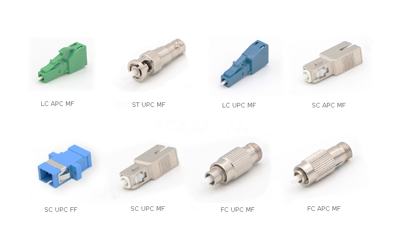
| Inline Attenuator | Installed between two fiber connectors (LC, SC, FC, etc.). | Patch panels, links between devices. |
| Plug-style (Male-Female) | Connects directly to an optical transceiver or adapter. | Protecting SFP, SFP+, XFP modules from overpower. |
How It Works
Absorbs or reflects a portion of the light signal to reduce power.Works like a "volume knob" for fiber optics, ensuring the receiver gets the right signal strength.
When to Use a Fiber Optic Attenuator?
✔ Short-distance links where signal power is too high.✔ Testing optical networks by simulating long-haul losses.
✔ Preventing damage to receivers in high-power laser systems.
✔ Balancing channels in wavelength-division multiplexing (WDM).
Using a fiber optic attenuator is straightforward, but proper handling ensures optimal performance and avoids signal issues. Here's a step-by-step guide:
1. Choose the Right Attenuator
Type: Fixed (set dB loss) or Variable (adjustable).Connector Type: LC, SC, FC, ST, etc. (must match your fiber connectors).
Wavelength Compatibility: Ensure it supports your system’s wavelength (e.g., 850nm, 1310nm, 1550nm).
Attenuation Level: Select the correct dB reduction (e.g., 5dB, 10dB).
2. Installation Steps
Power Off the optical equipment to prevent damage.Inspect Connectors for dirt or damage; clean with a fiber optic cleaner if needed.
Connect the Attenuator:
In-Line Type: Insert between two fiber patch cords (e.g., patch panel to transceiver).
Plug-Type (Male-Female): Attach directly to the optical transceiver’s TX port.
Secure Connections to avoid signal loss from misalignment.
3. Verify Performance
Use an optical power meter to check signal levels before and after attenuation.Ensure the output power is within the receiver’s optimal range (refer to equipment specs).
4. Safety & Maintenance
Avoid bending the fiber excessively (> minimum bend radius).Store unused attenuators in protective cases.
Recheck attenuation if network performance changes.
Common Applications
Prevent Receiver Saturation: Protects sensitive optics from overpower.Testing & Calibration: Simulates long-distance signal loss in lab setups.
Network Balancing: Equalizes power levels in WDM systems.
Troubleshooting
No Signal: Check for loose connections or incorrect attenuation level.High Insertion Loss: Clean connectors or replace a damaged attenuator.

评论
发表评论